When wood burns certain natural cycles are naturally completed: chemical energy turns into light and heat, water turns into steam and then rain, mineral salts transform into ashes and fall back down to the ground and carbon dioxide is given off into the air. But when wood burns properly, all this turns into energy which may be used creating less environmental impact than any fossil fuel (either oil or gas). It may seem strange, but burning wood and safeguarding nature are perfectly compatible.
This is the underlying philosophy of Schilling Power Station, which, together with the nearby sawmill, turn the woodburning cycle into something genuinely virtuous: waste products from the sawmill in the form of bark and wood chips become combustible biomass serving the power station. In turn, the power station generates energy in the form of heat to cover the sawmill’s energy requirements. This completes the circle, and that would be enough in its own right. But that is not all, because the extra energy generated is supplied to a nearby hospital, and the electricity produced could potentially supply up to 1450 detached houses in the surrounding neighbourhood.
Schilling Power Station shows how nature and technology can combine successfully, where technology means generating energy and nature provides the biomass required to serve this process (the biomass, which, as an alternative and renewable energy source, could provide at least 20% of the overall energy supply required by 2020).
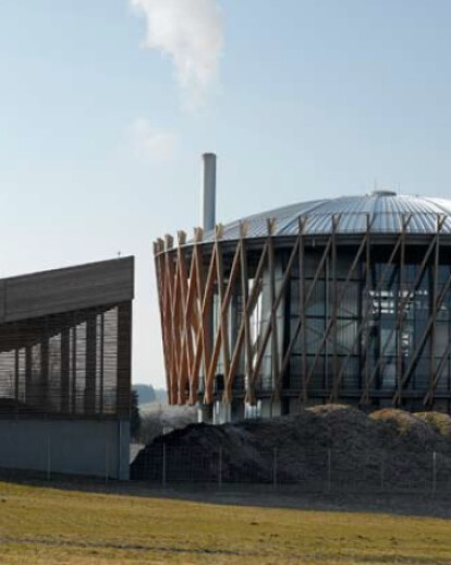
In architectural terms, this translates into an aesthetic form of ecology: transparency, lightness, stylistic clarity. A cube-shaped glass and steel core forms the case holding a visible technological heart that hides no secrets; a cylindrical coating made of planks of larch wood, woven around the core like some kind of craft texture, provides a natural, suspended filter with the outside environment; a semi-spherical dome made of zinc acts like a heavenly vaults on the roof; a sheet of water, on which everything rests, is a dematerialised rendition of what has been built: earth, air, water and fire set in the pure forms of a cube, cylinder and sphere. A geometric way of supplying clean energy at 0 km or, rather, 25 km, which is the maximum distance from which the Schilling sawmill obtains its wood supply.
The very same wood which, in other forms, the power station transforms into both an energy supply and decorative texture at the same time, drawing on a language also capable of communicating with all the surrounding country houses.
Purpose of the machine:
The purpose of the machine is to create heat energy for the wood drying machine and the space heater for the company Schilling in Schwendi. Another heat energy source leads to –Dietenbronn which supplies the clinic Dietenbronn GmbH which is specialist in Neurology. Untreated woods and bark so called NAWARO (unlimited natural resources) serve as combustibles.
Besides the heat generator, electricity is created in an ORC-machine (Organic Rankine Cycle) for the necessary heat. This concept ensures that heat is used in the most reasonable and technical way. The use of untreated wood instead of heating oil or natural gasoline causes a significant reduction in the CO2 burden of the atmosphere; this is additionally honoured through the NAWARO bonus for the production of electricity. The operations of an organic power station which has been adjusted to local demand will ensure not only a balanced CO2 level but also an economic business over decades.
The organic Power station Schilling in Schwendi generates a combustion capacity of 6.5 NW. The ORC-machine supplies electrical energy of 1.2 NW.
Construction of the machine:
The organic power station Schilling consists of four parts:
1.Loading 2.Combustion 3.Thermo oil circulation 4.ORC-machine
All four parts of the machine are automatically operated. The machine is electrically monitored and controlled by sensors and flow-operated safety devices. The operating conditions can be monitored and adjusted through a data visualisation using diagrams showing on the screens in the switch room. All procedures are constantly documented.
Loading:
The storage room for biomass is arranged with a new removing system, the so called `Walking Floor`. This system characterises through a simple construction without a carrier. The elements of transport are divided into groups of three. With every feed all groups are simultaneously moved forward by 100 mm by hydraulic cylinders. The pulling back of the groups happens individually, so that due to different frictional forces the materials are not pulled back as well. The closed surface of the push floor is free of carriers and squeezed sites. At the end the vertically inbuilt hydraulic running scraper above the cross conveyor serves for a consistent material charge. The fuel is transported subsurface through the power station and is passed on to a so called Stocker. The hydraulic ram puts the material portioned on the grate of combustion. Two valves prevent burn-back after every impulse. Two firefighting equipments have been installed.
Combustion:
Compared to a traditional wood stove the incinerator charge is almost burned residuefree. The material is moved across a number of zones. From the first part, the drying zone, material is moved to the second part where it is out gassed and burnt. In the third zone, the remaining wood charcoal glows out. At the end the ash and mineral fall into the ash conveyor the ash is moved from the fire box to a connected conveyor.
The combustion air has been pre-heated to 110°C which is then blown towards the incinerator charge. The combustion air hits the remains of the burnout and is continuously heated. The high temperature leads in the next section to the gassing out of the dried up incinerator charge. Explosive gasses are created which are burned through a primary air fan. The incinerator charge is almost dried completely using hot air, which is added by a secondary air fan. The remaining humidity is discharged with the flue gas. The combustion room temperature is cooled down to less than 1000°C by the adding of flue gas. This ensures that no environmental damaging nitrogen oxides are created and entrained ash is smelted.
In the combustion room on the located heat recovery boiler the flue gas passes the heat energy on to the thermo oil boiler. The oil is heated from 245°C to 315°C, the transferred heat energy lies by 5.3 MW. A second Economiser uses the flue gas to heat the thermo oil from the OCR-machine from 245°C to 254°C. At the same time the flue gas is cooled down from 245°C to 270°C. The transferred heat energy in the economiser lies by 800 kW. Another Economiser extracts another 800 kW from the flue gas, whereby parts of the thermo oil are heated from 110°C to 220°C, which are used to preheat the combustion air.
Following the flud gas goes into the Multizyclon where a huge amount of remaining ash is removed. The extra small ash particles are extracted using an electro filter. The induced draught fan transports the clean flue gas into the atmosphere through the chimney. Lambda oxygen sensors and thermo sensors monitor the combustible and air supply. Integrated measuring instruments monitor emissions and ensure the approved, but highly under cut emission levels.
Thermo oil circulation:
To transfer heat energy thermo oil is used. Three heat exchangers pass the hest energy from the thermo oil on to the hot water and silicon circulation
ORC-machine:
ORC stands for ‘Organic Rankine Cycle’. It is a steam turbine which does not operate on overheated water vapour but on steam withdrawn from an organic working material. Due to the working materials’ characteristics and the adjusted boiling point an ORC-machine is able to operate considerably more efficient in low ranges of performance than a turbine operating on water vapour. Because of the thermo dynamic characteristics of the used silicone oil the steam does not need to be overheated.
The machine operates on a compression between 9 and 11 bar compared to 30- 60 bar operating water vapour turbines. Lower requirements of the materials lead to cost reductions. In order to use the by thermo oil transported heat energy most effective and efficient there are five different parts of the machines that pass on the heat energy apart from the turbine, which transforms heat energy into movement.
a) Thermo oil which has been preheated from the heat recovery boiler to 315°C evaporates silicone oil in the evaporator. b) Silicone steam impels the turbine and a generator for electricity generation. Electric power of 1.2 MW. c) The silicone steam also heats up a huge amount of the liquid silicone oil, which is extracted through a feed water pump from the condenser. d) The silicone steam condenses and is cooled down in the cooled water heat exchanger. The condensed silicone steam comes through the feed water pump to the regenerator for the next operating cycle. Afterwards, the silicone oil is preheated in the Economiser 1 by thermo oil, from the evaporator, of 250°C. e) The cooling water from the condenser is used as heating water for the district heating network for the heat demand of the production plant Schilling. The heat gradient lies between 70°C and 90°C.
A rejection of heat from the condenser is physically unavoidable. Therefore, the concept of the ORC-machine has to make sure that heat rejection is reused. The OCRmachine is graded according to the usable heat. Ideal would be a constant demand of heat throughout the year (base load)


